Hy Jk02 M 5 Axis Interface Board Manual
Cheap Motor Driver, Buy Quality Home Improvement Directly from China Suppliers:5 Axis Breakout Board Stepper Motor Driver CNC Board + LCD Display + Handle (HY JK05 K6) Enjoy Free Shipping Worldwide! Limited Time Sale Easy Return. CNC Manual / Mach3 / HY-TB4DV-T Intelligent Four-Axis Drive Board Manual. HY-TB4DV-T Intelligent Four-Axis Drive Board Manual. Continue with reading or go to download page. Read Download.
- Printer Parallel Cable. (Male to Female)
This will be used to communicate from your computer to the breakout board via CNC control software.
- Mach3 Sample Configuration File
- Features
- Single Axis Toshiba 6560 Stepp Driver DIP Setting3a.Decay Setting:3b.Microstep Setting:3c.Current Settings:
- Pin Definitions of 5X Breakout Board
- Wiring Instruction
- Software Installation
- Homing Switch Wiring
- Emergency and Limit Switch Wiring
- Spindle Relay Wiring
Mach3 Sample Configuration File

You can download this file and put it under your Mach3 install folder. Launch Mach3 loader(not Milling or Turning), and select this profile to load the default settings for using ZTW 5X breakout board. This is just a sample configuration to get you started quickly. Please refer to Mach3 online documentation to adjust the settings as needed.
Sample Configuration file for Mach3[download]
- The breakout board is powered by a USB Cable (5V) (A Male - A Male USB Cable)
A USB cable is need to give power to the breakout board.It can be connected to a computer or our switchable power supply.
Features
- Compatible with Mach3, EMC2 Control Software
- Support up to 5 Axis stepper motor drivers
- Onboard spindle relay allows the on/off spindle control through Mach3 software
- 5 Input signal pins for homing, probing and EStop/Limit switches.
- Using USB for signal processing 5V power supply
- Parallel port communication between the driver board and desktop computer (with Parallel port)
Single Axis Toshiba 6560 Stepp Driver DIP Setting
Decay Setting:
- SW1 - OFF, SW2 - OFF - 0% Decay mode off
- SW1 - OFF, SW2 - ON - 25% Decat mode
- SW1 - ON, SW2 - OFF - 50% Decay mode
- SW1 - ON, SW2 - ON - 75% Decay mode
Microstep Setting:
- SW3 - OFF, SW4 - OFF 1 Microstep setting 200x1 = 200 steps per revolution
- SW3 - ON , SW4 - OFF 2 Microstep setting 200x2 = 400 steps per revolution
- SW3 - ON , SW4 - ON 8 Microstep setting 200x8 = 1600 steps per revolution (used by us as default settings)
- SW3 - OFF, SW4 - ON 16 Microstep setting 200x16 = 3200 steps per revolution
Current Settings:
- SW5 - ON , SW6 - ON 0.6A Current setting, not enough for our CNC Kit.
- SW5 - OFF, SW6 - ON 1.2A Current Setting, recommended for our 7x7, 7x12 model, using NEMA 17 steppers
- SW5 - ON , SW6 - OFF 1.5A Current Setting, recommended for our 12x12 model, using NEMA 23 steppers
- SW5 - OFF, SW6 - OFF 2.5A Current Setting, use this setting only if you need extra torque. Most cases, check your assembly, whether any alignment issue causing extra friction what requires more torque from the motors.
Pin Definitions of 5X Breakout Board
- Pin 1 - Enable
- Pin 2 - Motor 1 Step
- Pin 3 - Motor 1 Dir
- Pin 4 - Motor 2 Step
- Pin 5 - Motor 2 Dir
- Pin 6 - Motor 3 Step
- Pin 7 - Motor 3 Dir
- Pin 8 - Motor 4 Step
- Pin 9 - Motor 4 Dir
- Pin 10 - Input Signal, can be used for estop and limit switches
- Pin 11 - Input Singal, can be used for X homing
- Pin 12 - Input Singal, can be used for Y homing
- Pin 13 - Input Singal, can be used for Z homing
- Pin 14 - Input Signal, can be used for Spindle on/off control
- Pin 15 - Input Signal, can be used for probing
- Pin 16 - Motor 5 Step
- Pin 17 - Motor 5 Dir
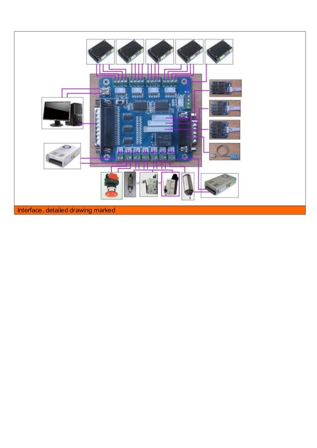
Wiring Instruction
DIAGRAM.jpg
This diagram can be used as a reference throughout this tutorial.
DSCN7145.jpgStep 001:Along with your recently purchased ZTW breakout board package, you will also need a male-male usb cord, stepper motors, and parallel port cable. You will also need some wires to connect everything together.
DSCN7146.jpgStep 002:Let’s start by connecting a piece of 4-wire cable to the breakout board. Be sure the ends are stripped and the wire is exposed approximately ¼”. Start by connecting to one of the 3 front terminal blocks.
DSCN7147.jpgStep 003:Be sure to tighten down the terminal screws snug enough so they will not pull out. I have the colors coordinating as follows: Black=EN , Green=DIR , Yellow=STEP , Red=COM
DSCN7148.jpgStep 004:Do the same procedure for the other 2 terminals, being sure to keep the color order the same for each. This will make things easier later.
DSCN7149.jpgStep 005:Now we can connect the other end of the wires to the stepper drivers. We will start with X and then move onto the other 2.
DSCN7152.jpgStep 006:Now, when connecting to the driver board, I used the following color sequence: Yellow=PUL- , Red=PUL+ , Black=EN- , Green=DIR-
DSCN7153.jpgStep 007:Now, since the COM terminal on the breakout board is positive, we want to connect all the positive terminals on the stepper driver with jumper wires. So, start by inserting a jumper with our red wire and snug the screw down.
DSCN7154.jpgStep 008:Now we will want to insert the previous jumper, along with another new jumper into EN+ together
DSCN7155.jpgStep 009:Lastly, insert the remaining jumper end into DIR+. Essentially all we have done is connected PUL+, EN+, and DIR+ all together.
DSCN7156.jpgStep 010:Here you can see all the connections.
DSCN7157.jpgStep 011:Now we can do the same procedure for Y. Start by connecting the breakout board to the Y-Driver board the same as was done for the X.
DSCN7158.jpgStep 012:Now connect all the jumper wires between the “+” terminals again.
DSCN7160.jpgStep 013:Follow the same procedure for a third time for the Z-Axis. You now should have all 3 stepper drivers connected to the breakout board.
DSCN7161.jpgStep 014:Next, grab your power supply. I will be using our 12-24V switching supply, but the 12V supply included in the kit work the same way.
DSCN7163.jpgStep 015:Connect the power supply to one of the driver boards. Be sure to get the positive from the power supply to the “+” on the driver board and negative from the power supply to the “-“ on the driver board. Don’t tighten the screws down just yet.
DSCN7164.jpgStep 016:We now need to add two jumper wires to the previous connection. I will use the black jumper for the negative and the yellow for the positive 12V. Plug those in and now go ahead and tighten the terminal screws, being sure both wires are tight and don’t pull out.
DSCN7165.jpgStep 017:Run the other end of the jumper wires into the positive and negative on the next driver board. Along with those, insert another set of jumpers in order to connect the third driver board.
DSCN7166.jpgStep 018:We now essentially have the 12V power supply connected to all three driver boards.
DSCN7168.jpgStep 019:Here is the final setup.
DSCN7169.jpgStep 020:If you are using the switchable power supply or any other, be sure it is set up for 12V.
DSCN7171.jpgStep 021:Now we can go ahead and connect your male to male USB cord to the power supply (or computer if your power supply does not have a port). This cable is not used for any data transfer, just for power.
DSCN7172.jpgStep 022:Connect the other end of the cable to your breakout board.
DSCN7174.jpgStep 023:Here is what should be connected at this time.
DSCN7176.jpgStep 024:Now, grab one of your stepper motors and let’s determine the wiring. Detailed specs on our Shinano Stepper Motors can be found here http://www.shinano.com/motors/stepper.html
DSCN7177.jpgStep 025:Begin touching pairs of wires together with an ohm meter to determine which pairs of wires are connected to each other. Once you get 2 wires that give a resistance, keep them together (this will give us the “A” pair and the “B” pair.
DSCN7178.jpgStep 026:Here I have separated the 2 pairs of wires. The colonel's bequest for mac.
DSCN7180.jpgStep 027:Now plug in the “B” pair to the stepper driver. (Which pair is “A” and “B” does not matter at this time.)
DSCN7182.jpgStep 028:Finish by connecting the “A” pair to the stepper driver. Perform the last 5 steps over again for the other 2 motors.
DSCN7183.jpgStep 029:Go ahead now and plug your parallel cable from your computer into the breakout board.
DSCN7184.jpgStep 030:Connect your power supply’s power cable.
DSCN7185.jpgStep 31:Connect the power supply to the wall. You are now finished with the hardware installation. Next we will work on the software.
Software Installation
01.jpgStep 001:Start up Mach3.
02.jpgStep 002:You may want to create a new profile here. I created one called “Zen Breakout board”.
03.jpgStep 003:You should now have Mach3 page opened up.
04.jpgStep 004:Click the “config” tab, then choose “ports and pins”.
05.jpgStep 005:Choose the “motor outputs”, and be sure to copy the settings that you see in the above screen shot. If after completing this entire tutorial, your directions are reversed, you can return to this page and click the “Dir LowActive” for the axis that is moving the wrong direction.
06-1.jpgStep 006:Now choose the “input signals” tab and copy the settings above over.
07.jpgStep 007:Scroll down a little ways until you see the “Estop” signal. Be sure and copy these settings for the Estop.
08.jpgStep 008:Lastly choose the “output signals” tab and copy over these settings. Then you can click “apply” and “OK”. You should now have the proper settings to run Mach3.
NOTE: If this is your first time setting up Mach3, you should check out our other wiki pages on configuring Mach3’s settings.
Homing Switch Wiring
Homeswitches.jpg
Use the above diagram to wire up your homing switches. This method of wiring will work with the way we just set up Mach3. There are several ways to go about doing this, so this is just one example.The switches shown here are wired in the 'normally open' position. If you do not have these exact switches, you can use a ohm meter to determine which 2 terminals are normally open. Basically touch the two terminals to the ohm meter, when the switch is depressed the ohm meter should display 0.00 Ohms.
Emergency and Limit Switch Wiring
Limit-Estopswitches.jpg
Use the above diagram to connect your limit and emergency stop switches. Each of the switches gets one terminal connected to the common ground, and the other terminal gets connected to the Emergency/Limit terminal on the breakout board. Like before, there are several ways to do this and this is just one example. All of these switches are wired in their normally open position just as before. If you purchased your emergency stop mushroom switch from us, you can wire it exactly as shown. Otherwise, use an ohm meter to determine which terminals are used for the normally open setup. The setup of Mach3 performed earlier will work properly with this wiring method.
Spindle Relay Wiring
SpindleRelay.jpg
Use the above diagram to wire your spindle if you would like to be able to turn it on and off via Mach3. This setup utilizes the breakout board's onboard relay to act as a switch. The relay is controlled via Mach3 to in turn control your spindle. If you set up Mach3 as shown previously, you will be able to utilize the relay to turn on and off your spindle.
I just ordered one like this off ebay USA for under $15 including shipping.£15.99 + £3.50 shipping from GuildfordI like the design of it because it has four terminals for each motor drive, making wiring simpler than having to connect several wires to a single point like you do with BOBs that only have separate terminals for half the control lines. This BOB has support for 5 axes, a relay control for spindle on/off or other device, USB and wire terminals for power, a control pendant input and three connectors for 3, 4 or 5 axis digital readout.Here's a manual for it. Simpler wiring is why I bought it. Might get a control pendant sometime for easy jogging of the mill.This is the cheap cheap one that came with the motors and drives I bought. Supposedly supports six axes, have seen it setup with all the + control lines tied to the +5V input OR all the - control lines tied to GND at the bottom right in that picture. Seems like a good way to get everything fried if there's a spike on the +5V or GND where half the wires are all connected.-Original Message-From: aaron mooreSent: Wednesday, September 18, 2013 9:06 AMTo: EMC userslistSubject: Emc-users Breakout boardHICan anyone suggest a good cheap breakout board, available inUK to run withLinuxcnc (of course) that makes it easy for an idiot to wirehome and E stop switches.CheersAaron. On Wed, 18 Sep 2013 10:23:34 +0100, you wrote:On 18 September 2013 07:06, aaron moore wrote: Can anyone suggest a good cheap breakout board, available in UK to run with Linuxcnc (of course) that makes it easy for an idiot to wire home and E stop switches.I haven't used it, butlooks like it will do all that you require.Don't order from Zapp via the website.Ring up and order because they have form for taking money then emailingyou that the item is not in stock.
I have been caught out twice withthat, last item took 5 weeks from order and they had taken the money viathe website on date of order!!Steve Blackmore. Attachments:On 9/18/2013 12:16 PM, Alex Joni wrote: Hrmmm, I was kinda in a hurry when I read the original email, so somehow I assumed the question was for a BBB breakout board / aka cape.Are you working on a LPT breakout for the BeagleBone?!?If so, that's great! I just started looking into designing one ofthese, along with an interface board for the RAMPS.Pinout for step/dir/limit generally doesn't matter, but I am hoping toalso be able to support a MESA parallel port interface board and run thehm2 driver on the 'Bone. For that, the data lines all need to be inbanks where their GPIO direction bit can be set by the PRU safelywithout using an atomic read-modify-write. It looks like the block ofGPIO bank 1 pins, from bits 12-19 would work, and as a plus they are alltogether so an 8-bit byte doesn't have to get splintered into a bunch ofgroups spread across several GPIO banks.-Charles Steinkuehlercharles@.